how to check, the ebike controller is working or not?
pratik r. sonawane
aug 08, 2021
related topics
the ebike controller is an essential component used in electric bikes. without a controller or driver, bldc motors are not possible to run.
if suddenly the controller stopped working then how to know what are the problems in the controller?. is there any procedure or method to check, does the controller need repairing or replacing? in this article, you will learn by using some basic methods about how to check, the ebike controller is working or not.
the list of components require
multimeter (any type)
controller
battery
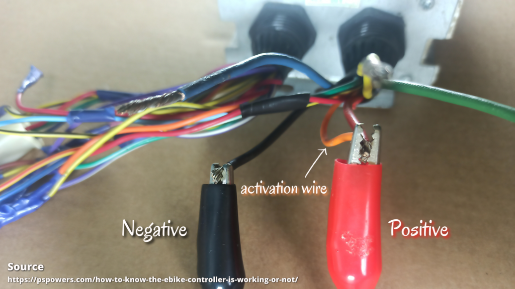
step 1: connect the battery with the controller.
fig. A: battery or external power supply connected with controller
first, connect the battery (I’m using an external power supply) with the controller as well as the activation wire present in the controller.
what is the function of activation or key switch wire:
it is used to activate the functions of other wires. depending upon the type of the controller its color may differ for different drivers.
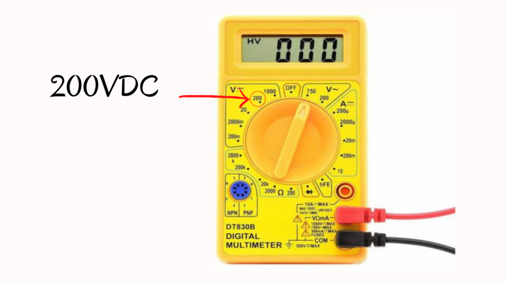
step 2: set multimeter reading
fig, B : setting of multimeter reading
set multimeter reading on 200VDC. with the help of a multimeter, check the voltage across the controller’s negative and positive wires.
it should be close to the battery supply.
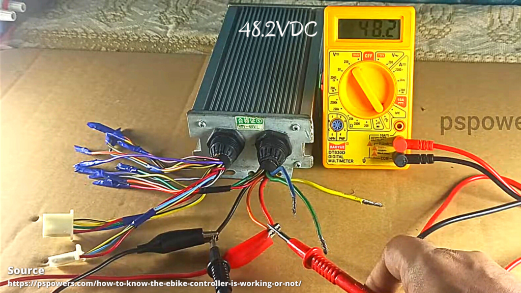
fig. C: checking input voltage at positive and negative terminal of controller
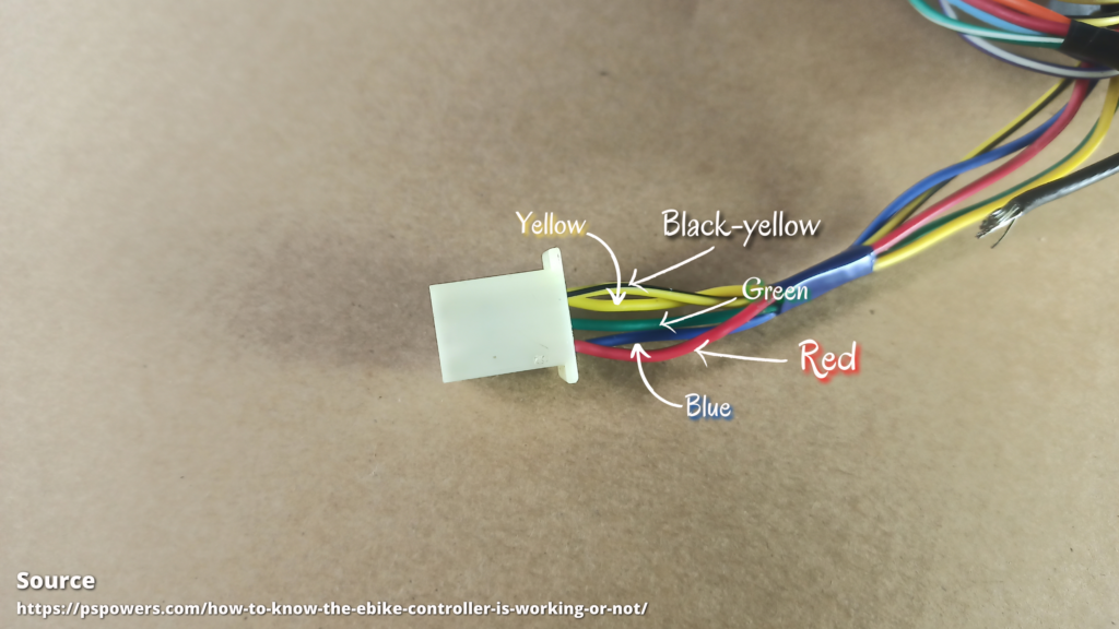
step 3: check the hall sensor, pin group.
fig, D: hall sensor wire group
every driver has the same number/color of a group of hall sensor wire.
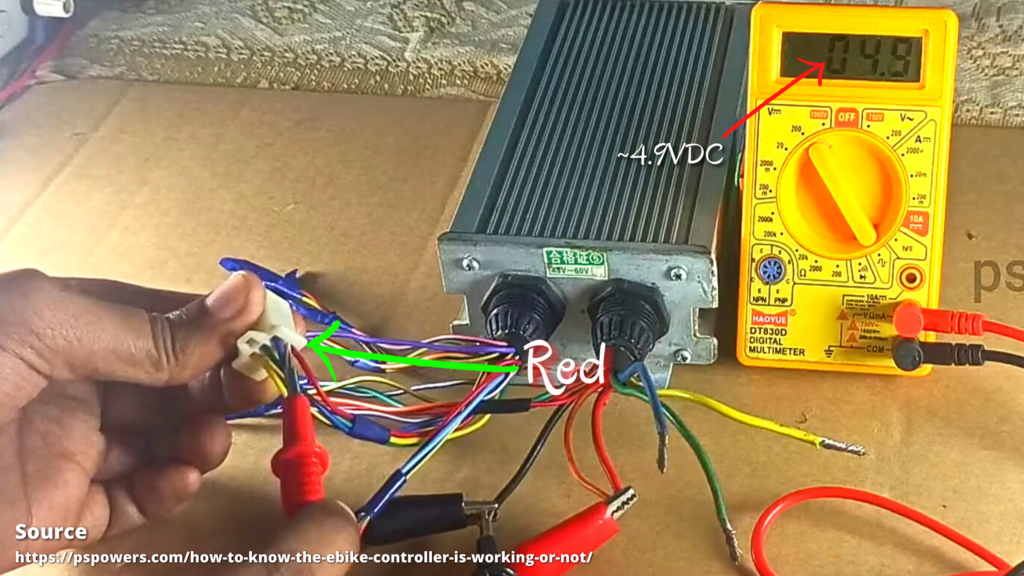
now connect the negative wire(black wire) of the controller with black wire of multimeter (grounded) and another terminal to the positive supply of hall sensor wire.
it will show voltage around 4.9-5VDC.
fig, E: checking hall voltage at red wire
if not then internally, the controller has a hall voltage issue.
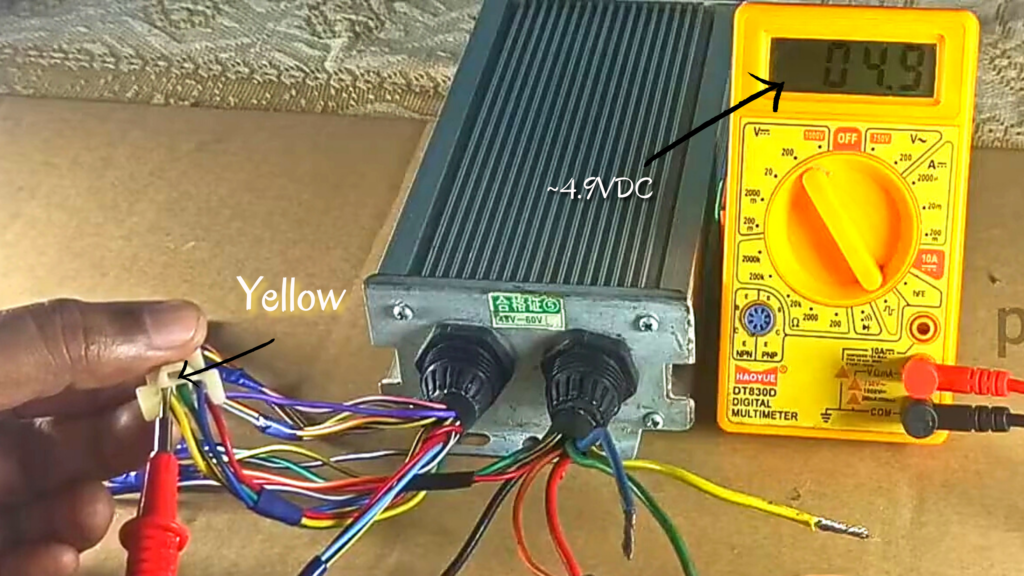
now follow the same to other color wire
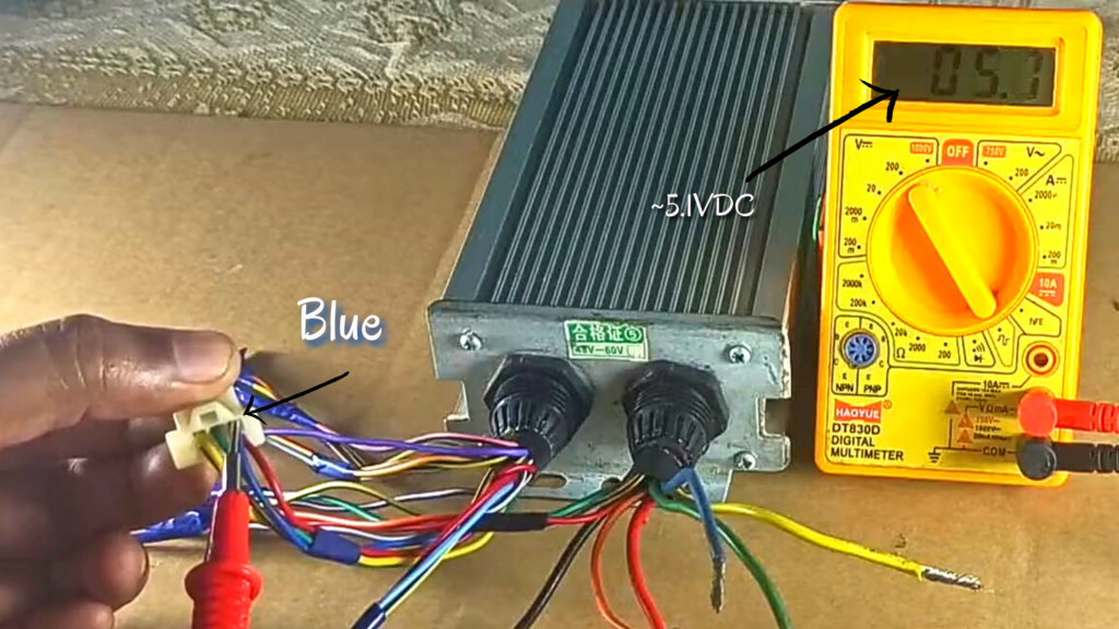
check the voltages at yellow, blue, and green
it should be between 4.5-5VDC.
fig. F: checking hall voltage at yellow wire
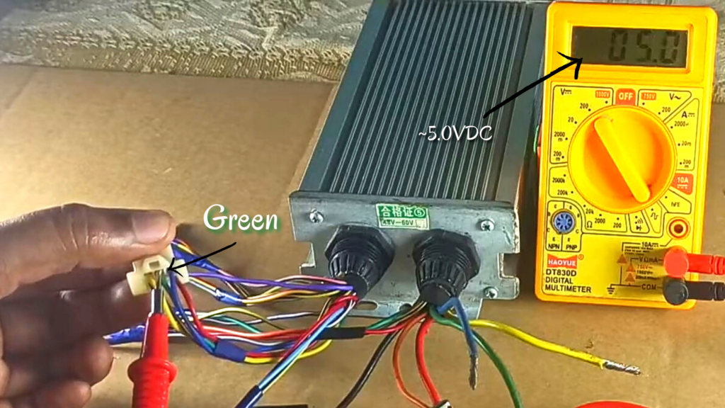
fig. G: checking hall voltage at green wire
fig. H: checking hall voltage at blue wire
if you didn’t get any reading from above, it means that some functions are not working and the controller needs to be replaced or repair.
also, check if the motor hall sensors are working or not!
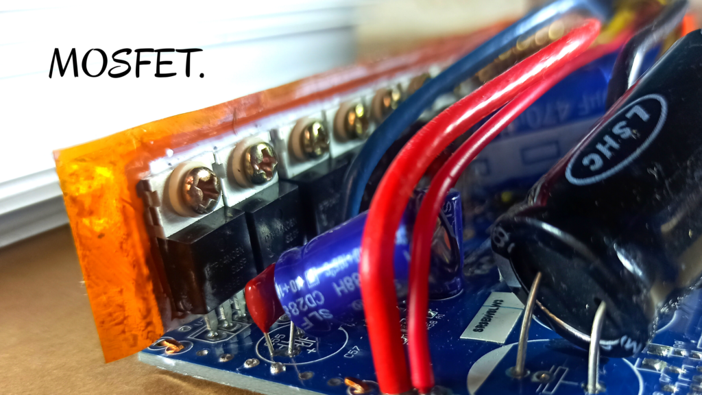
step 4: check the controller MOSFETs
fig. I: checking mosfets
set multimeter reading on diode/buzzer/continuity.
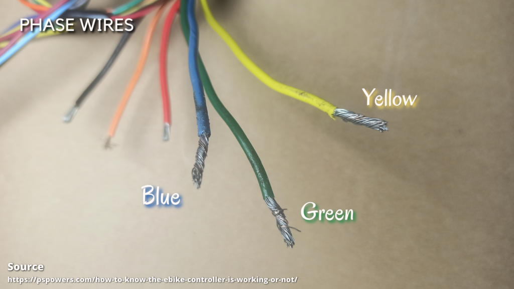
now connect a positive terminal of the multimeter with the negative wire and another terminal with phase wires (green, yellow, blue) of the controller.
fig. J: checking phase wires of controller
check each phase wire of the controller. it must have to show some ohmic resistance range from 415-490ohm.
which is depends on the type of controller.
if it doesn’t show you ohmic resistance that means one of the MOSFETs is damaged internally and needs a replacement.
so this is the way you can find whether the controller is working or not. you can apply this method to any type of controller.
Time's up
article by
author name
Lorem ipsum dolor sit amet, consectetur adipiscing elit. Ut elit tellus, luctus nec ullamcorper mattis, pulvinar dapibus leo.